HOME
|
THE PROCHEM ADVANTAGE
|
CONTACT US
|
LINKS
PIPING PRODUCTS
INSTRUMENTATION
VALVES AND ACTUATORS
MANUFACTURING
INDENT SERVICE
HYDRAULIC
Registered Users
–
Sign In
Search Catalog
By Keyword
By Item #
CAD Products
Dielectric Male Connectors: DCM
CAD Products
>
Tube Fittings & Pipe Fittings
>
Gyrolok Tube Fittings
>
Dielectric Tube Fittings
>
Item # 6DCM4-316
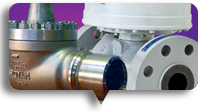
Item # 6DCM4-316, Dielectric Male Connectors: DCM
Download PDF
Download PDF
Printable Page
Email This Page
Save To Favorites
Please wait…
Specifications
·
Features & Benefits
·
Application
Specifications
Material
316 Stainless Steel
T - Tube O.D.
3/8
in
larger image
A
3.66
in
B - Hex Flat
11/16
in
C - Hex Flat
5/8
in
Cx - Hex Flat
13/16
in
D
.72
in
E Min
.28
in
F
.83
in
G
3.32
in
Features & Benefits
Features:
Thermoplastic Insulators with:
Resistance in excess of 108 ohms at 70° F (21°C) and 50% relative humidity.
Resistance in excess of 106 ohms at 100° F (38°C) and 90% relative humidity.
Metal components made of 316 Stainless Steel:
Appropriate orifice for fitting size (e.g. .422” orifice in 1/2” fitting):
HOKE Gyrolok tube fitting ends:
Benefits:
Maximum safety and protection to critical monitoring station instrumentation.
Long component life in rugged environment.
Maximum flow capability provided by all sizes of HOKE Gyrolok Dielectric tube fittings.
The unique value and performance offered by HOKE Gyrolok.
Application
Commonly used in the Natural Gas Transmission industry, the Dielectric Fitting will prevent current flow resulting from Impressed Current Cathodic Protection Systems, static electricity or even lightning strikes, from reaching sensitive monitoring station equipment.
Impressed Current Cathodic Protection Systems involve the application of a low voltage, low amperage direct current to a pipeline and eventual transfer of corrosive effects to a typically underground anode bed.
If the current flow is not interrupted before reaching the monitoring station critical equipment could be damaged or rendered inaccurate.
By installing HOKE’s Gyrolok Dielectric Tube Fitting on impulse lines between the pipeline and the monitoring station, current flow is interrupted while full fluid flow is permitted.
MORE IMAGES
·
Gas Transmission Typical Application
DOWNLOADS
Catalogs & Assembly Instructions
PIPING PRODUCTS
INSTRUMENTATION
VALVES AND ACTUATORS
MANUFACTURING
INDENT SERVICE
HYDRAULIC
Sales Inquiry
The New Hoke Online Catalogue
Technical Reference Links
Working at Prochem
Our Training Initiatives
Contact us through Our Network
Useful Product Links
FAQs
Disclaimer
Privacy Statement
Site by
Loaded